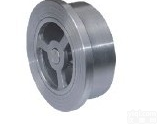
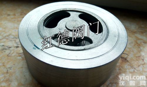
H71 对夹单瓣升降式止回阀-不锈钢对夹单瓣升降式止回阀
- 型号:H71
- 产地:上海
- 供应商:上海光高阀门有限公司
- 供应商报价:1100
- 标签:对夹单瓣升降式止回阀-不锈钢对夹单瓣升降式止回阀,1100,上海光高阀门有限公司

产品名称:【对夹式止回阀】
产品型号:【H76】【H71】
【对夹蝶式止回阀】【对夹单瓣升降式止回阀】【对夹单瓣旋启式止回阀(超薄型)】【凸耳对夹双瓣旋启式止回阀】
对夹式止回阀(One-way valve):止回阀又称单向阀或逆止阀,其作用是防止管路中的介质倒流。水泵吸水关的底阀也属于止回阀类。止回阀按结构划分,可分为升降式止回阀、旋启式止回阀和蝶式止回阀三种。升降式止回阀可分为立式和卧式两种。旋启式止回阀分为单瓣式、双瓣式和多瓣式三种。蝶式止回阀为直通式、以上几种止回阀在连接形式上可分为螺纹连接、法兰连接和焊接三种。 启闭件靠介质流动和力量自行开启或关闭,以防止介质倒流的阀门叫止回阀。止回阀属于自动阀类,主要用于介质单向流动的管道上,只允许介质向一个方向流动,以防止发生事故。
对夹式止回阀的参数:
1.传动:自动
2.连接:内螺纹、外螺纹、法兰、焊接、对夹式、卡箍、卡套
3.结构:升降式,旋启式
4.密封:软密封、硬密封、衬胶、衬氟等。
5.压力:0.6Mpa≤64.0Mpa
6.口径:DN15≤DN800
7.温度:0℃≤550℃
8.阀体材料:不锈钢、铸钢、碳钢、铸铁等。
9.适用介质:水、油品、蒸汽等。
止回阀原理:
对夹式止回阀是指依靠介质本身流动而自动开、闭阀瓣,用来防止介质倒流的阀门,又称逆止阀、单向阀、逆流阀、和背压阀。止回阀属于一种自动阀门,其主要作用是防止介质倒流、防止泵及驱动电动机反转,以及容器介质的泄放。止回阀还可用于给其中的压力可能升至超过系统压的辅助系统提供补给的管路上。止回阀主要可分为旋启式止回阀(依ZX旋转)与升降式止回阀(沿轴线移动)。 止回阀的作用是只允许介质向一个方向流动,而且阻止反方向流动。通常这种阀门是自动工作的,在一个方向流动的流体压力作用下,阀瓣打开;流体反方向流动时,由流体压力和阀瓣的自重合阀瓣作用于阀座,从而切断流动。
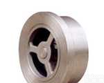
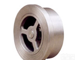
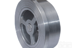
H76型凸耳对夹双瓣旋启式止回阀(美标) H71对夹升降式止回阀(国标)H71 wafer type lift check valve(GB standard) H76型凸耳对夹双瓣旋启式止回阀(美标) H71对夹升降式止回阀(国标)H71 wafer type lift check valve(GB standard)
对夹单瓣升降式止回阀产品名称:H71对夹单瓣升降式止回阀 产品材料:WCB、CF3、CF8、CF3M、CF8M 产品规格:DN15~400、PN10~100 产品简介:
H76 type lug and wafer type double discs swing check valve(ANSI standard)
H71对夹式降式止回阀(美标)H71 wafer type lift check valve(ANSI standard) 公称压力
PN(MPa)
Norminal
pressure公称通径
DN(mm)
Norminal
diameter尺寸(mm)Dimension 重量(kg)
Weight配管法兰(供参考)
Flange(as referenced) L D D3 D2 螺栓孔中
心圆直径D1
Diameter of the bolt螺栓数量
Quantity of
the bolt
螺栓直径d
Diameter
of the bolt螺栓长度L1
Length of
the bolt 4.0 15 16 52 15 44 0.12 65 4 M12 80 20 19 62 19 52 0.24 75 4 M12 90 25 22 72 24 60 0.34 85 4 M12 90 32 28 83 31 72 0.53 100 4 M16 110 40 31.5 93 39 74 0.80 110 4 M16 115 50 40 109 48 98 1.2 125 4 M16 125 65 46 129 63 117 2.2 145 8 M16 135 80 50 144 78 128 3.1 160 8 M16 145 100 60 168 98 / 9 190 8 M20 160 125 90 196 123 / 14 220 8 M24 205 150 106 224 148 / 18 250 8 M24 225 200 140 291 198 / 28 320 12 M27 275 250 160 353 248 / 42 385 12 M30 295 6.4 15 25 62 15 / 0.5 75 4 M12 100 20 31.5 73 19 / 0.7 90 4 M16 115 25 35.5 83 24 / 1.0 100 4 M16 130 32 40 89 31 / 1.3 110 4 M20 140 40 45 104 39 / 2.0 125 4 M20 150 50 56 114 48 / 3.2 135 4 M20 160 65 63 138 63 / 4.5 160 8 M20 170 80 71 148 78 / 5 170 8 M20 180 100 80 174 98 / 7 200 8 M24 200 125 110 211 123 / 13 240 8 M27 245 150 125 248 148 / 22 280 8 M30 270 200 160 310 198 / 40 345 8 M33 325 250 180 362 248 / 60 400 8 M33 350 10.0 15 25 62 15 / 0.6 75 4 M12 100 20 31.5 73 19 / 1.0 90 4 M16 115 25 35.5 83 24 / 1.3 100 4 M16 130 32 40 89 31 / 1.6 110 4 M20 140 40 45 104 39 / 2.5 125 4 M20 150 50 56 120 48 / 3.8 145 4 M24 172 65 63 144 63 / 6 170 8 M24 185 80 71 154 78 / 7 180 8 M24 195 100 80 181 98 / 10 210 8 M27 220 125 110 218 123 / 18 250 8 M30 265 150 125 258 148 / 30 290 12 M30 285 200 160 324 198 / 56 360 12 M33 345 250 180 392 248 / 70 430 12 M36 365
压力级
Pressure
rating口径DN 尺寸(mm)Dimension 重量
(kg)
Weight配管法兰(供参考)Flange(as referenced) NPS DN L D D3 D2 螺栓孔中
心圆直径D1
Diameter of the bolt螺栓数量
Quantity of
the bolt螺栓直径d
Diameter of the bolt螺栓长度L1
Length of
the bolt in mm Class150 1/2 15 16 46 15 44 0.12 60.5 4 1/2 M14 90 3/4 20 19 56 19 52 0.24 70 4 1/2 M14 100 / 25 22 65 24 60 0.34 79.5 4 1/2 M14 110 1 1/4 32 28 74 31 72 0.53 89 4 1/2 M14 120 1 1/2 40 31.5 84 39 74 0.80 98.5 4 1/2 M14 130 2 50 40 103 48 98 1.2 120.5 4 5/8 M16 145 2 1/2 65 46 122 63 117 2.2 139.5 4 5/8 M16 160 3 80 50 135 78 128 3.1 152.5 4 5/8 M16 170 4 100 60 173 98 - 5.8 190.5 8 5/8 M16 180 5 125 90 195 123 - 12 216.0 8 3/4 M20 210 6 150 106 220 148 - 17 241.5 8 3/4 M20 230 8 200 140 277 198 - 29 298.5 8 3/4 M20 270 10 250 160 337 248 - 35 362.0 12 7/8 M24 290 Class300 1/2 15 25 52 15 - 0.3 66.5 4 1/2 M14 100 3/4 20 31.5 65 19 - 0.46 82.5 4 5/8 M16 110 / 25 35.5 72 24 - 0.6 89 4 5/8 M16 120 1 1/4 32 40 81 31 - 0.8 98.5 4 5/8 M16 130 1 1/2 40 45 94 39 - 1.5 114.5 4 3/4 M20 140 2 50 56 110 48 - 2.4 127.0 8 5/8 M16 150 2 1/2 65 63 128 63 - 3.0 149.0 8 3/4 M20 170 3 80 71 148 78 - 4.0 168.5 8 3/4 M20 190 4 100 80 179 98 - 5.5 200.0 8 3/4 M20 200 5 125 110 214 123 - 13 235.0 8 3/4 M20 240 6 150 125 249 148 - 22 270.0 12 3/4 M20 260 8 200 160 305 198 - 36 330.0 12 7/8 M24 310 10 250 180 359 248 - 40 387.5 16 1 M27 330 Class600 1/2 15 25 52 15 - 0.3 66.5 4 1/2 M14 100 3/4 20 31.5 65 19 - 0.46 82.5 4 5/8 M16 110 / 25 35.5 72 24 - 0.6 89.0 4 5/8 M16 120 1 1/4 32 40 81 31 - 0.8 98.5 4 5/8 M16 130 1 1/2 40 45 94 39 - 1.5 114.5 4 3/4 M20 140 2 50 56 110 48 - 2.4 127.0 8 5/8 M16 150 2 1/2 65 63 128 63 - 3.0 149.0 8 3/4 M20 170 3 80 71 147 78 - 4.0 168.5 8 3/4 M20 190 4 100 80 191 98 - 5.5 216.0 8 3/4 M24 200 5 125 110 239 123 - 13 267.0 8 3/4 M27 240 6 150 125 264 148 - 22 292.0 12 3/4 M27 290 8 200 160 318 198 - 36 349.0 12 7/8 M30 350 10 250 180 398 248 - 40 432.0 16 1 M33 370 Class900 1/2 15 25 62 25 15 0.6 82.5 4 3/4 M20 125 3/4 20 31.5 69 30 19 0.9 89.0 4 3/4 M20 135 1 25 35.5 77 36 24 1.2 101.5 4 7/8 M24 155 1 1/4 32 40 87 43 31 1.5 111.0 4 7/8 M24 160 1 1/2 40 45 97 52 39 2.0 124.0 4 1 M27 175 2 50 56 140 62 48 5.5 165.0 8 7/8 M24 195 2 1/2 65 63 162 75 62 7.5 190.5 8 1 M27 215 3 80 71 165 90 76 8 190.5 8 7/8 M24 210 4 100 80 204 112 95 14 235.0 8 1 1/8 M30 245 5 125 110 245 125 110 27 279.5 8 1 1/4 M33 290 6 150 125 286 150 127 41 317.5 12 1 1/8 M30 310 8 200 160 356 200 165 76 393.5 12 1 3/8 M36 375 产品材料:WCB、CF3、CF8、CF3M、CF8M 产品规格:DN15~400、PN10~100 产品简介:
H76 type lug and wafer type double discs swing check valve(ANSI standard)
H71对夹式降式止回阀(美标)H71 wafer type lift check valve(ANSI standard) 公称压力
PN(MPa)
Norminal
pressure公称通径
DN(mm)
Norminal
diameter尺寸(mm)Dimension 重量(kg)
Weight配管法兰(供参考)
Flange(as referenced) L D D3 D2 螺栓孔中
心圆直径D1
Diameter of the bolt螺栓数量
Quantity of
the bolt
螺栓直径d
Diameter
of the bolt螺栓长度L1
Length of
the bolt 4.0 15 16 52 15 44 0.12 65 4 M12 80 20 19 62 19 52 0.24 75 4 M12 90 25 22 72 24 60 0.34 85 4 M12 90 32 28 83 31 72 0.53 100 4 M16 110 40 31.5 93 39 74 0.80 110 4 M16 115 50 40 109 48 98 1.2 125 4 M16 125 65 46 129 63 117 2.2 145 8 M16 135 80 50 144 78 128 3.1 160 8 M16 145 100 60 168 98 / 9 190 8 M20 160 125 90 196 123 / 14 220 8 M24 205 150 106 224 148 / 18 250 8 M24 225 200 140 291 198 / 28 320 12 M27 275 250 160 353 248 / 42 385 12 M30 295 6.4 15 25 62 15 / 0.5 75 4 M12 100 20 31.5 73 19 / 0.7 90 4 M16 115 25 35.5 83 24 / 1.0 100 4 M16 130 32 40 89 31 / 1.3 110 4 M20 140 40 45 104 39 / 2.0 125 4 M20 150 50 56 114 48 / 3.2 135 4 M20 160 65 63 138 63 / 4.5 160 8 M20 170 80 71 148 78 / 5 170 8 M20 180 100 80 174 98 / 7 200 8 M24 200 125 110 211 123 / 13 240 8 M27 245 150 125 248 148 / 22 280 8 M30 270 200 160 310 198 / 40 345 8 M33 325 250 180 362 248 / 60 400 8 M33 350 10.0 15 25 62 15 / 0.6 75 4 M12 100 20 31.5 73 19 / 1.0 90 4 M16 115 25 35.5 83 24 / 1.3 100 4 M16 130 32 40 89 31 / 1.6 110 4 M20 140 40 45 104 39 / 2.5 125 4 M20 150 50 56 120 48 / 3.8 145 4 M24 172 65 63 144 63 / 6 170 8 M24 185 80 71 154 78 / 7 180 8 M24 195 100 80 181 98 / 10 210 8 M27 220 125 110 218 123 / 18 250 8 M30 265 150 125 258 148 / 30 290 12 M30 285 200 160 324 198 / 56 360 12 M33 345 250 180 392 248 / 70 430 12 M36 365
压力级
Pressure
rating口径DN 尺寸(mm)Dimension 重量
(kg)
Weight配管法兰(供参考)Flange(as referenced) NPS DN L D D3 D2 螺栓孔中
心圆直径D1
Diameter of the bolt螺栓数量
Quantity of
the bolt螺栓直径d
Diameter of the bolt螺栓长度L1
Length of
the bolt in mm Class150 1/2 15 16 46 15 44 0.12 60.5 4 1/2 M14 90 3/4 20 19 56 19 52 0.24 70 4 1/2 M14 100 / 25 22 65 24 60 0.34 79.5 4 1/2 M14 110 1 1/4 32 28 74 31 72 0.53 89 4 1/2 M14 120 1 1/2 40 31.5 84 39 74 0.80 98.5 4 1/2 M14 130 2 50 40 103 48 98 1.2 120.5 4 5/8 M16 145 2 1/2 65 46 122 63 117 2.2 139.5 4 5/8 M16 160 3 80 50 135 78 128 3.1 152.5 4 5/8 M16 170 4 100 60 173 98 - 5.8 190.5 8 5/8 M16 180 5 125 90 195 123 - 12 216.0 8 3/4 M20 210 6 150 106 220 148 - 17 241.5 8 3/4 M20 230 8 200 140 277 198 - 29 298.5 8 3/4 M20 270 10 250 160 337 248 - 35 362.0 12 7/8 M24 290 Class300 1/2 15 25 52 15 - 0.3 66.5 4 1/2 M14 100 3/4 20 31.5 65 19 - 0.46 82.5 4 5/8 M16 110 / 25 35.5 72 24 - 0.6 89 4 5/8 M16 120 1 1/4 32 40 81 31 - 0.8 98.5 4 5/8 M16 130 1 1/2 40 45 94 39 - 1.5 114.5 4 3/4 M20 140 2 50 56 110 48 - 2.4 127.0 8 5/8 M16 150 2 1/2 65 63 128 63 - 3.0 149.0 8 3/4 M20 170 3 80 71 148 78 - 4.0 168.5 8 3/4 M20 190 4 100 80 179 98 - 5.5 200.0 8 3/4 M20 200 5 125 110 214 123 - 13 235.0 8 3/4 M20 240 6 150 125 249 148 - 22 270.0 12 3/4 M20 260 8 200 160 305 198 - 36 330.0 12 7/8 M24 310 10 250 180 359 248 - 40 387.5 16 1 M27 330 Class600 1/2 15 25 52 15 - 0.3 66.5 4 1/2 M14 100 3/4 20 31.5 65 19 - 0.46 82.5 4 5/8 M16 110 / 25 35.5 72 24 - 0.6 89.0 4 5/8 M16 120 1 1/4 32 40 81 31 - 0.8 98.5 4 5/8 M16 130 1 1/2 40 45 94 39 - 1.5 114.5 4 3/4 M20 140 2 50 56 110 48 - 2.4 127.0 8 5/8 M16 150 2 1/2 65 63 128 63 - 3.0 149.0 8 3/4 M20 170 3 80 71 147 78 - 4.0 168.5 8 3/4 M20 190 4 100 80 191 98 - 5.5 216.0 8 3/4 M24 200 5 125 110 239 123 - 13 267.0 8 3/4 M27 240 6 150 125 264 148 - 22 292.0 12 3/4 M27 290 8 200 160 318 198 - 36 349.0 12 7/8 M30 350 10 250 180 398 248 - 40 432.0 16 1 M33 370 Class900 1/2 15 25 62 25 15 0.6 82.5 4 3/4 M20 125 3/4 20 31.5 69 30 19 0.9 89.0 4 3/4 M20 135 1 25 35.5 77 36 24 1.2 101.5 4 7/8 M24 155 1 1/4 32 40 87 43 31 1.5 111.0 4 7/8 M24 160 1 1/2 40 45 97 52 39 2.0 124.0 4 1 M27 175 2 50 56 140 62 48 5.5 165.0 8 7/8 M24 195 2 1/2 65 63 162 75 62 7.5 190.5 8 1 M27 215 3 80 71 165 90 76 8 190.5 8 7/8 M24 210 4 100 80 204 112 95 14 235.0 8 1 1/8 M30 245 5 125 110 245 125 110 27 279.5 8 1 1/4 M33 290 6 150 125 286 150 127 41 317.5 12 1 1/8 M30 310 8 200 160 356 200 165 76 393.5 12 1 3/8 M36 375
更多对夹式止回阀同类请点击光在未来-高在品质 光高竭诚为您服务!